Facts About Wedge Barriers Revealed
Wiki Article
Some Ideas on Wedge Barriers You Need To Know
Table of ContentsThe smart Trick of Wedge Barriers That Nobody is Talking AboutThe Of Wedge Barriers
Wedge Barriers for Dummies
g., springtime assistance 65 )might be fixed to completion of the spring pole 58 to allow compression of the springtimes 60. As the springtimes 60 are compressed between the springtime supports 62, the springtime setting up 54 generates a pressure acting on the web cam paired to the springtime pole 58 in a direction 66. As an example, the continuing to be force put on the camera to deploy the wedge plate 16 might be offered by an electromechanical actuator 84 or other actuator. The spring setting up 54 and the actuator 84(e. g., electromechanical actuator)might run together to equate the webcam and raise the wedge plate 16.
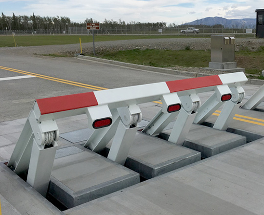
As mentioned above, the spring assembly 54 exerts a constant pressure on the cam, while the electromechanical actuator might be controlled to apply a variable force on the web cam, therefore allowing the lifting and decreasing( i. e., releasing and retracting )of the wedge plate 16. In specific personifications, the continuous pressure used by the spring assembly 54 might be adjustable. g., electromechanical actuator) is impaired. As will be appreciated, the springtime setting up 54 might be covered and protected from debris or various other aspects by a cover plate(e. g., cover plate 68 revealed in FIG. 4) that may be considerably flush with the raised surface area 38 of the foundation 14. As stated above, in the deployed setting, the wedge plate 16 serves to obstruct access or travel past the obstacle 10. As an example, the obstacle 10(e. g., the wedge plate 16 )may obstruct pedestrians or lorries from accessing a property or path. As view it now talked about over, the barrier 10 is connected to the support 30 safeguarded within the foundation 14,

front braces 71. As an outcome, the linkage assemblies 72 may pivot and rotate to make it possible for the collapse and expansion of the link assemblies 72 throughout retraction and deployment of the bather 10. The link assemblies 72 cause activity of the wedge plate 16 to be restricted. For instance, if a vehicle is traveling towards the deployed wedge plate 16(e. For instance, in one condition, the safety legs 86 may be prolonged duringmaintenance of the obstacle 10. When the safety legs 86 are deployed, the safety legs 86 support the weight of the wedge plate 16 against the surface area 12. As a check my blog result, the lifting system 50 may be shut down, serviced, eliminated, changed, and so forth. FIG. 5 is partial viewpoint view of an embodiment of the surface-mounted wedge-style barrier 10, highlighting the cam 80 and the cam surface areas 82 of the training device 50. Particularly, 2 web cam surfaces 82, which are referred to as reduced cam surface areas 83, are placed below the webcam 80. The lower camera surface areas 83 might be taken care of to the surface area 12 (e. For instance, the reduced webcam surface areas 83 and the placing plate 85 may develop a single piece that is protected to the support 30 by screws or other mechanical fasteners. additional resources Furthermore, two camera surfaces 82, which are described as top web cam surface areas 87, are positioned over the webcam 80 and combined to (e. In other embodiments, interfering layers or plates might be positioned between the surface 12 and the lower web cam surfaces 83 and/or the wedge plate 16 and the upper cam surface areas 87 As mentioned over, the camera 80 converts along the cam surfaces 82 when the wedge plate 16 is lifted from the pulled back position to the released placement. In addition, as pointed out above, the springtime setting up 54 (see FIG. 3 )might give a force acting on the web cam 80 in the instructions 102 via springtime pole 58, which may reduce the force the electromechanical actuator 84 is called for to relate to the web cam 80 in order to actuate and raise the wedge plate 16. 1 )to the released placement(see FIG. 4). As shown, the web cam 80 consists of track wheels 104(e. g., rollers), which call and equate along the cam surfaces 82 during operation.
Report this wiki page